Make production transparent. Try MDCplus
Try it yourself Get guided demo12 August 2026
How Do You Build a 3D Shop Floor Map Driven by Live PLC Data?
Building a 3D shop floor map with React Three Fiber: preparing CAD geometry for the web, mapping PLC tags to mesh colors, performance limits, and when 3D is the wrong choice.
How Do You Build a 3D Shop Floor Map Driven by Live PLC Data?
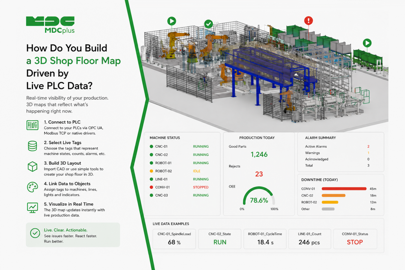
Short answer: export a heavily simplified factory layout from CAD to glTF, load it with React Three Fiber, and map named meshes to PLC tags so mesh color reflects live machine state. The hard part isn't the 3D rendering — that's well-trodden ground with good libraries. It's getting CAD geometry light enough to run in a browser, and establishing a reliable link between a mesh in the model and a tag in the PLC. This article covers both, plus an honest section on when a 3D map is the wrong answer entirely.
Copy this prompt to get started
Build a React Three Fiber component that loads a glTF factory layout model and colors machine meshes based on live status data.
Requirements: load the glTF with
useGLTFand suspend properly while loading. Machine meshes are identified by their name property, which follows the convention [describe yours, e.g. "MACHINE_<id>"]. Accept a status object keyed by machine ID and set each matching mesh's material color from it: running, idle, fault, and a distinct fourth state for no-data.Constraints: do not create a new material per frame or per status change — reuse material instances and mutate color. Use OrbitControls with damping, constrained so the camera cannot go below the floor plane. Include a fixed top-down "reset view" button. Render machine labels as HTML overlays rather than 3D text. Handle the case where a status key has no matching mesh, and where a mesh has no matching status — log both rather than failing silently. End with a list of assumptions you made.
Contents:
- When 3D earns its place — and when it doesn't
- Getting CAD geometry into the browser
- The naming convention that makes everything work
- Feeding it live PLC data
- Mapping state to visual treatment
- Performance: the constraints that actually bite
- Camera and interaction design
- Common pitfalls
- Frequently asked questions
- Conclusion
When 3D earns its place — and when it doesn't
Worth settling first, because 3D shop floor maps are disproportionately likely to be built because they look impressive in a demo rather than because they answer a question better than a grid of tiles would.
| 3D is genuinely better when | A 2D grid is better when |
|---|---|
| Physical location matters — finding a machine in a large unfamiliar plant | Viewers already know where every machine is |
| Spatial relationships explain the problem (material flow, congestion, adjacency) | The question is "what's the status," not "where" |
| The audience is visitors, executives, or new staff | The audience is operators glancing between tasks |
| You're planning layout changes or simulating flow | You need it readable at distance on a wall |
Note the last row specifically: a 3D map is a poor Andon display. It requires interpretation time, doesn't survive the squint test, and the constraints covered in our piece on designing Andon displays are largely incompatible with a perspective 3D view. These are different tools for different jobs.
It's also worth being precise about terminology: this is a spatial visualization, not a digital twin in the simulation sense. A genuine digital twin models behavior and can predict outcomes, as covered in our manufacturing digital twin guide. Calling a colored 3D map a digital twin internally sets expectations it won't meet.
Getting CAD geometry into the browser
This is where most of these projects actually stall. A factory CAD model is built for engineering precision and routinely contains millions of triangles, every bolt and cable tray modeled. Loading that directly into a browser produces a page that takes a minute to load and runs at three frames per second, if it loads at all.
The pipeline that works:
- Simplify aggressively in CAD before exporting. Delete internal geometry, fasteners, piping, and anything not visible from a walking viewpoint. A machine can usually be a recognizable box with a couple of distinguishing features.
- Export to glTF/GLB — the web-native 3D format, far better suited than STEP or IGES, which browsers can't use directly.
- Compress the result. Draco geometry compression and texture compression typically cut file size dramatically with little visible difference at the zoom levels a floor map is viewed at.
- Target a budget. As a rough starting point, aim for a total model well under 100k triangles and a few megabytes for a floor map viewed on ordinary hardware. If you're an order of magnitude above that, simplify further rather than optimizing the renderer.
A useful reframe: you are building a map, not a rendering. Nobody needs to see the machine's model number embossed on its housing — they need to recognize which box is machine 14 and see what color it is.
The naming convention that makes everything work
The single most consequential decision in this whole project is how a mesh in the glTF file is linked to a machine in your data. Get this right and the rest is mechanical; get it wrong and you'll be maintaining a hand-written lookup table forever.
The approach that scales is naming meshes in CAD according to a convention that encodes the machine identifier — MACHINE_CNC014, matching the ID your monitoring system uses. Then the mapping is a string operation rather than a maintained mapping file, and adding a machine to the floor means naming it correctly in CAD, not editing application code.
Where CAD naming can't be changed, the fallback is a configuration file mapping mesh names to machine IDs — workable, but it becomes a second thing to keep in sync, and it will drift. Push for the naming convention if you have any influence over the CAD source.
Feeding it live PLC data
The 3D component should not talk to a PLC. It should consume a plain status object — machine ID to state — from whatever data layer you already have, exactly as any other dashboard component would.
Where that comes from depends on your setup: a monitoring platform API polled every few seconds, an MQTT subscription for push updates, or, if you're reading PLC registers directly, a bridge service in front of Modbus TCP or a similar protocol — the same bridge pattern described in our piece on getting OPC UA data into Retool.
Two things worth constraining explicitly. First, update rate: a floor map showing machine states does not need 60fps data. Once or twice per second is more than sufficient, and pushing high-frequency updates into a scene graph is a needless performance cost. Second, the no-data state must be distinct from any real machine state, for the same reason it matters everywhere else — a green machine that stopped reporting ten minutes ago is actively misleading.
Mapping state to visual treatment
- Color is the primary channel, but not the only one. The colorblindness constraints from Andon design apply here too; consider a small floating icon above faulted machines rather than relying on red alone.
- Reserve motion for genuine urgency. A pulsing or flashing mesh draws the eye across the whole scene, which is exactly right for a fault and exactly wrong for anything routine.
- Emissive material for status, not just base color. A machine lit from within reads clearly under scene lighting; relying on base color alone means status appears to change with camera angle and shadows.
- Keep non-machine geometry visually quiet. Walls, floors, and fixtures should be desaturated so machine status is the only thing carrying color in the scene.
Performance: the constraints that actually bite
- Never create materials or geometries inside the render loop. The most common performance bug in generated Three.js code. Create once, mutate properties afterward.
- Reuse material instances across machines with the same state. Four shared status materials beat two hundred individual ones.
- Use instancing for repeated geometry. If forty identical machines appear in the layout, instanced meshes render dramatically faster than forty separate ones.
- Render on demand, not continuously. A floor map that only redraws when data changes or the camera moves uses a fraction of the GPU of one looping at 60fps — which matters a great deal if it's running all day on a modest floor PC.
- Dispose properly. Geometries, materials, and textures need explicit disposal when unmounted, or a page that navigates between views will leak GPU memory until the tab dies.
That last point deserves emphasis for factory use specifically: this display may run for weeks without a reload. Leaks that are invisible in a five-minute demo become a crashed screen on a Sunday night.
Camera and interaction design
Free-orbit cameras are disorienting for non-technical users, who reliably end up underneath the floor or staring at a wall with no idea how to recover. Constrain the camera: prevent it from going below floor level, limit zoom range, and always provide a prominent "reset view" control.
Beyond that, a few patterns worth prompting for: a top-down default view (most legible for finding a machine), click-to-select opening a detail panel with that machine's metrics, and HTML overlay labels rather than 3D text — overlays stay readable at any camera angle and cost nothing to render, while 3D text rotates away from the viewer and is expensive.
Common pitfalls
- Loading unsimplified CAD. The number one project killer. Simplify before exporting, not after loading.
- Hand-maintained mesh-to-machine mapping. Works for ten machines, becomes a liability at a hundred, and silently drifts as the floor changes.
- Building it as an Andon replacement. Different tool, different job; the 3D map won't survive the squint test.
- Unconstrained camera. Users get lost, then stop using it.
- Memory leaks on long-running displays. Invisible in testing, fatal in production.
- No plan for keeping the model current. Shop floors get rearranged. A 3D map showing last year's layout is worse than none, because it sends people to the wrong place.
Frequently asked questions
Do I need the original CAD files, or can I build the layout from scratch?
Building simple box geometry from a 2D floor plan is a completely legitimate approach and often faster than wrestling a detailed CAD model into web-ready shape. For a status map, recognizable placement matters far more than geometric fidelity.
How often should the 3D map poll for machine status?
Once or twice per second is ample for a status map. Higher rates add cost without adding value, since nobody perceives a status change faster than that in a spatial view they have to scan.
Will this run on the kind of PC we have on the shop floor?
It depends heavily on model complexity and whether the machine has a usable GPU. This is a strong argument for aggressive simplification and render-on-demand: a lightweight scene runs comfortably on modest hardware, while an unsimplified one won't run acceptably anywhere.
Is a 3D floor map the same thing as a digital twin?
No. A digital twin models behavior and supports simulation or prediction; a 3D map with live status colors is a spatial visualization. Both are useful, but conflating them creates expectations the map can't meet.
Conclusion
A 3D shop floor map is a genuinely good fit for a specific job — helping people find machines and understand spatial relationships in a large or unfamiliar plant — and a poor fit for the glance-and-go job an Andon board does. If it's the right tool, the two decisions that determine success are made before any 3D code is written: how aggressively the CAD geometry is simplified, and how mesh names map to machine IDs. Get those right, keep the component consuming a plain status object, and watch for the memory leaks that only surface after a display has been running for a week.
Related articles:
- Manufacturing Digital Twin Guide
- How Do You Design an Andon Display Operators Can Read from 10 Meters?
- How Do You Get Live OPC UA Machine Data into Retool?
- Modbus TCP for Machine Monitoring
- MDCplus Machine Connectivity & Integrations
About MDCplus
Our key features are real-time machine monitoring for swift issue resolution, power consumption tracking to promote sustainability, computerized maintenance management to reduce downtime, and vibration diagnostics for predictive maintenance. MDCplus's solutions are tailored for diverse industries, including aerospace, automotive, precision machining, and heavy industry. By delivering actionable insights and fostering seamless integration, we empower manufacturers to boost Overall Equipment Effectiveness (OEE), reduce operational costs, and achieve sustainable growth along with future planning.
Ready to increase your OEE, get clearer vision of your shop floor, and predict sustainably?
Other articles
14.08.2026
How Do You Build a Mobile Dashboard Plant Managers Actually Use?
Building a mobile-first Tailwind PWA for plant managers: what belongs on a phone screen, offline behavior, push notifications, and prompts for an executive manufacturing dashboard
Read more
13.08.2026
How Do You Create Manufacturing KPI Widgets with Cursor and v0.dev?
Using v0.dev to generate manufacturing KPI widgets and Cursor to wire them into an existing dashboard repo: the two-tool workflow, prompts for scrap rate and MTTR/MTBF, and integration pitfalls
Read more
12.08.2026
How Do You Build a 3D Shop Floor Map Driven by Live PLC Data?
Building a 3D shop floor map with React Three Fiber: preparing CAD geometry for the web, mapping PLC tags to mesh colors, performance limits, and when 3D is the wrong choice.
Read more
11.08.2026
How Do You Design an Andon Display For Shop-Floor Using AI?
Prompting UI/UX for shop floor Andon displays: type scale for distance viewing, colorblind-safe status coding, glare and glove constraints, and prompts that produce factory-ready screens
Read more
10.08.2026
How Do You Get Live OPC UA Machine Data into Retool?
How to vibe-code a Retool custom component that streams live OPC UA machine data over WebSockets: the bridge service, security boundaries, and prompts for each layer
Read more